Update 2026/06/01: This work has been published at SIGBOVIK 2026!
Last time, I showed you how to implement Conway’s Game of Life in Clip Studio Paint. In this second instalment of Using Digital Art Programs for Unintended Purposes, I present you with a working computer programmed using Adobe Photoshop Actions.
To be specific, this computer is a Turing machine—an abstract machine capable of running any computer algorithm. I’ll show you how to create this machine by using layer blend modes and the Invert command to perform logical computations. Let’s begin!
Performing boolean operations with layer blend modes
Before creating a computer, we must start with some basic building blocks—the boolean operations AND, OR, and NOT. As a refresher:
ANDreturns 1 if both of its inputs are 1.ORreturns 1 if at least one of its inputs is 1.NOTnegates its input—1 becomes 0 and vice versa.
To implement boolean operations in an image manipulation program like Photoshop, we will represent 0 and 1 by a black and a white square, respectively.

Applying the NOT operation to these squares is simple: just use the Invert command by clicking Image > Adjustments > Invert (or pressing Ctrl-I). This command inverts the colours of the active layer, turning white into black and vice versa.
What about AND and OR? To implement these, we’ll use layer blend modes. As I briefly discussed in the Game of Life post, layers are components of a Photoshop file that can be arranged and adjusted independently. Each pixel in a layer has three colour channels—red, green, and blue—which range from 0 to 1. Black is represented by three 0’s, while white is represented by three 1’s. Layer blend modes are used to blend two layers by combining the values of their colour channels.
We’ll focus on two layer blend modes today:
Multiply, which multiplies the pixel values of the two layers. I.e., if the two values are x and y, the final value is xy.Screen, which inverts the two values, multiplies them together, and inverts the result. I.e., if the two pixel values are x and y, the final value is 1–(1–x)(1–y).
Both blend modes apply to the three colour channels separately.
Multiply and Screen blend modes.Notice that the result of Multiply is white if both input layers are white. On the other hand, the result of Screen is white if at least one layer is white. In other words, Multiply and Screen act like the AND and OR operators! So, if we wanted to AND two inputs, we would:
- Copy those inputs to new layers, and stack the layers on top of each other.
- Set the top layer’s blend mode to
Multiply. - Merge the two layers together (by clicking Layer > Merge Layers or pressing
Ctrl-E).
Multiply layer to perform the AND operation.All that copying and merging could get tedious. Fortunately, Photoshop allows us to record the process and save it as an Action, which can be accessed via the Window > Actions menu. This enables us to calculate the output with just one click.
AND operation with a single click via an Action.Now, we can run arbitrary boolean computations in Photoshop with ease! And that’s all we need to implement more complex machines.
Implementing a multiplexor
Let’s start with something simple: a 2-input multiplexor, which outputs one of its two inputs depending on the value of a given selector. In our Photoshop file, we’ll create two input squares, IN0 and IN1; an output square, OUT; and a selector square, S.
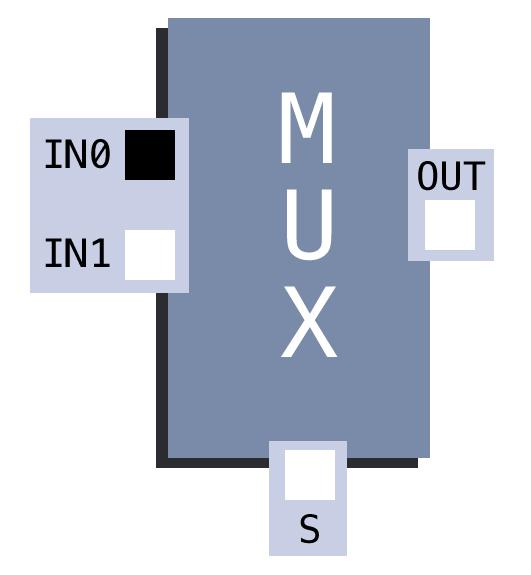
We want OUT to reflect IN0 if S is black and IN1 if S is white. In other words, OUT should be white if and only if S is black and IN0 is white OR S and IN1 are both white. To put it in equation form:
OUT = ((NOT S) AND IN0) OR (S AND IN1)
We run this computation in Photoshop by performing the following steps:
- Copy
StoOUT, and Invert the copiedS. - Copy
IN0toOUT, set the copiedIN0toMultiply, and merge it with the copiedSto create(NOT S) AND IN0. - Copy
StoOUTagain. - Copy
IN1toOUT, set the copiedIN1toMultiply, and merge it with the copiedSto createS AND IN1. - Set
S AND IN1toScreen, and merge it with(NOT S) AND IN0.
Whew! That’s a lot of copying and moving, but we can save it all into a single Photoshop Action.
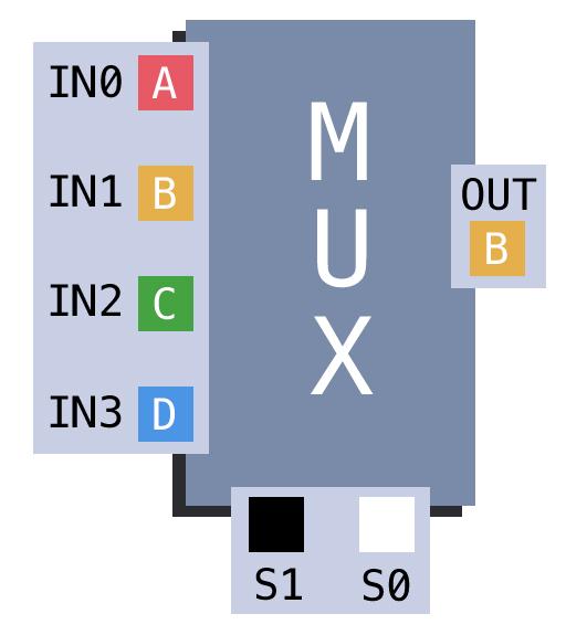
S is black, the multiplexor copies IN0 to OUT; otherwise, it copies IN1 to OUT.Now we have a 2-input multiplexor! Note that this multiplexor functions correctly even if the input colours are not limited to black or white. We can also extend it to take four inputs and two selectors—implementation is left as an exercise to the reader.
Using Difference and Threshold to create an equality comparator
Let’s try building something else: an equality comparator, which outputs white if the inputs are equal and black otherwise. In equation form:
OUT = ((NOT IN0) AND (NOT IN1)) OR (IN0 AND IN1)
We could implement this in a similar way as the multiplexor. But what if we wanted to support coloured inputs, not just black and white? A straightforward implementation wouldn’t work in this case.
The Difference blend mode comes to the rescue! As the name says, this mode computes the colour difference between two layers, resulting in black if the two colours are the same.
Difference blend mode.If the two colours are different, the result will be some colour other than black. We can force this colour to be white by applying the Threshold adjustment, found in Image > Adjustments, with a Threshold Level of 1.
If we apply the Difference blend mode to the inputs and then apply a Threshold, the output will be black if the inputs are identical and white otherwise. Invert the output, and we have an equality comparator! Both equality comparators and multiplexors will be used to build our Photoshop Turing Machine.
OUT to white if IN0 and IN1 are equal; otherwise, it sets OUT to black.How to build a Turing machine
We’re finally ready to build a Turing machine. If you’re unfamiliar with how Turing machines work, don’t worry; I’ll explain it as we go.
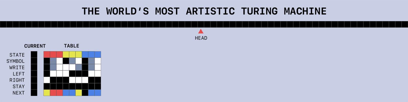
A Turing machine contains an infinitely long tape stretching in both directions. The tape is divided into cells, and a head points to the cell that is currently “active.” Each cell is either blank or contains a symbol, typically the binary digit 0 or 1. On our Photoshop Turing Machine tape, we will interpret a black cell as a blank, a grey cell as the symbol 0, and a white cell as the symbol 1. (Note that this differs from our previous definition of pixel values, where a black cell represented 0.)

1011, which represents the decimal number 11. The head points to the last 1 in the string.Along with the tape, a Turing machine has a current state (which we also represent with a colour). To program a Turing machine, we begin with providing a starting state and a set of rules, one for every combination of state and symbol. Each rule specifies a symbol, direction (left, right, or stay), and next state. At each step, the machine decides which rule to follow based on the current state and symbol in the active cell. Then, based on the rule, the machine performs three actions:
- Write the specified symbol in the active cell.
- Move the tape in the specified direction.
- Set the current state to the next one specified.
This process continues until the machine hits a “halt” state (which we represent with black). Amazingly, any computer algorithm can be implemented with these simple rules!
In our Photoshop Turing Machine, we present rules in a table. Each column in the table has seven coloured cells, which specify the following:
- The current
STATEand activeSYMBOLrequired for the machine to follow this rule. - The symbol that the machine should
WRITEto the tape. - The direction in which the tape should move, indicated by colouring one cell white among the cells
LEFT,RIGHT, andSTAY. - The
NEXTstate.
We also create a separate CURRENT column, used to hold the active rule.
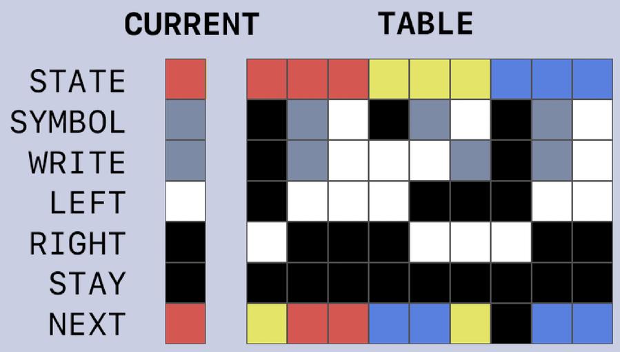
CURRENT column for our Photoshop Turing Machine. This particular set of rules adds 1 to the number on the tape. The currently active rule is for the state “red” and symbol “grey.”Combine the rule table with the tape, and we have a full Turing machine!
Running the Turing machine
To run our Turing machine, we first specify the starting state by filling in the NEXT cell of the CURRENT column. Then, for each machine step, we do the following:
- Use an equality comparator to determine which rule’s
STATEandSYMBOLequal the current ones. - Copy the correct rule into the
CURRENTcolumn, using the comparator’s results as the selection input to a multiplexor. - Copy the current
WRITEsymbol into the active tape cell. - Move the tape according to the current
LEFT,RIGHT, andSTAYvalues. This can be done by creating a left-shifted, a right-shifted, and a stationary copy of the tape, then choosing which copy to keep via a multiplexor that takesLEFT,RIGHT, andSTAYas its selection input. - Use the state in the
NEXTcell of theCURRENTcolumn for the next step.
We package these moves into a single “Step Turing Machine” Action. Unfortunately, I haven’t figured out how to make the machine halt automatically, so we’ll just have to keep clicking “Step Turing Machine” until we see the halt state. But other than that, we now have a working Turing machine! A link to all the Photoshop files and Actions is here if you want to try them out yourself (they’ve been tested with Photoshop 2022).
1011) on the tape and set the starting state to red. After several “Step Turing Machine” actions, the machine outputs 12 (1100).Final thoughts (+ bonus Photoshop Machine: an adder)
While experimenting with Photoshop Actions, I also created this adder, which takes two 3-bit binary inputs and outputs their sum. On the right, it features a seven-segment display that updates in sync with the inputs and output.
The adder didn’t quite fit in with the rest of the post, but I thought it was worth mentioning anyway. It’s included in the Photoshop files if you want to take a look.
It took 34 Actions containing a total of 257 individual steps for me to implement the adder, while the Turing machine took 19 Actions and 149 individual steps. In both cases, I avoided repeating steps by calling Actions from within other Actions. When possible, I also placed multiple squares on the same layer in such a way that boolean operations could be computed “in parallel.”
I hope you’ve enjoyed exploring the interesting possibilities of Photoshop Actions with me! Perhaps you even have your own fun ideas for this unusual programming method. Thanks for reading, and see you next time!